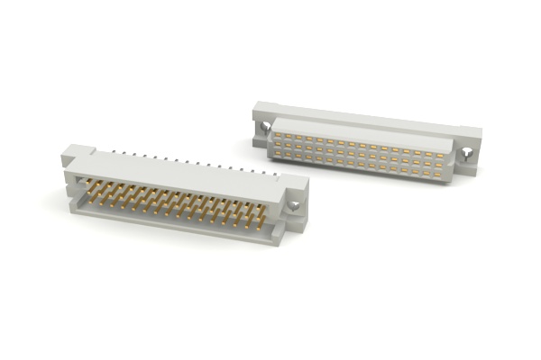
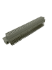
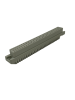
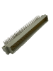
DIN 41612 Connectors
All products in this category are RoHS & REACH Compliant
| Product Photo | Part Number | Mating Parts | Gender | Contact Positions | Mounting Orientation | Body Type | Centerline | Terminals | Options | Datasheet / 3D Model | Sample Ordering |
|---|---|---|---|---|---|---|---|---|---|---|---|
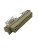
| DIN-240FR-L44-A1 | Female | 4 Rows: 100, 128, 160, 200, 240 | Right Angle PCB Mount | Long Body (4 Rows): A, B, C, & D Loaded | .100" | .157" Solder Tail | View | View | |||
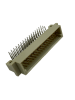
| DIN-240MS-L44-A1 | Male | 4 Rows: 100, 128, 160, 200, 240 | Straight PCB Mount | Long Body (4 Rows): A, B, C, & D Loaded | .100" | .157" Solder Tail | High Temp Insulator | View | View | ||
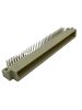
| DIN-32FR-S22-A1C1 | Female | 2 Rows: 16, 32 | Right Angle PCB Mount | Long Body (2 Rows): A & B Loaded | .100" | .157" Solder Tail | View | View | |||
| DIN-32FS-S22-A1C1 | Female | 2 Rows: 16, 32 | Straight PCB Mount | Long Body (2 Rows): A & B Loaded | .100" | .157" Solder Tail | View | View | |||
| DIN-32MR-S22-A1C1 | Male | 2 Rows: 16, 32 | Right Angle PCB Mount | Long Body (2 Rows): A & B Loaded | .100" | .157" Solder Tail | View | View | |||
| DIN-32MS-S22-A1C1 | Male | 2 Rows: 16, 32 | Straight PCB Mount | Long Body (2 Rows): A & B Loaded | .100" | .157" Solder Tail | View | View | |||
 |
DIN-48FR-S33-A1C1 | Female | 3 Rows: 16, 32, 48 | Right Angle PCB Mount | Short Body (3 Rows): A, B, & C Loaded | .100" | .157" Solder Tail | View | View | ||
| DIN-48FS-S33-A1C1 | Male | 3 Rows: 16, 32, 48 | Straight PCB Mount | Short Body (3 Rows): A, B, & C Loaded | .100" | .157" Solder Tail | View | View | |||
 |
DIN-48MR-S33-A1C1 | Male | 3 Rows: 16, 32, 48 | Right Angle PCB Mount | Short Body (3 Rows): A, B, & C Loaded | .100" | .157" Solder Tail | View | View | ||
| DIN-48MS-S33-A1C1 | Male | 3 Rows: 16, 32, 48 | Straight PCB Mount | Short Body (3 Rows): A, B, & C Loaded | .100" | .157" Solder Tail | View | View | |||
| DIN-64FR-L22-A1C1 | Female | 2 Rows: 32, 64 | Right Angle PCB Mount | Long Body (2 Rows): A & B Loaded | .100" | .157" Solder Tail | View | View | |||
| DIN-64FS-L22-A1C1 | Female | 2 Rows: 32, 64 | Straight PCB Mount | Long Body (2 Rows): A & B Loaded | .100" | .157" Solder Tail | View | View | |||
 |
DIN-64MR-L22-A1C1 | Male | 2 Rows: 32, 64 | Right Angle PCB Mount | Long Body (2 Rows): A & B Loaded | .100" | .157" Solder Tail | View | View | ||
| DIN-64MS-L22-A1C1 | Male | 2 Rows: 32, 64 | Straight PCB Mount | Long Body (2 Rows): A & B Loaded | .100" | .157" Solder Tail | View | View | |||
 |
DIN-96FR-L33-A1C1 | Female | 3 Rows: 32, 64, 96 | Right Angle PCB Mount | Long Body (3 Rows): A & C Loaded | .100" | .157" Solder Tail | View | View | ||
 |
DIN-96FS-L33-A1C1 | Female | 3 Rows: 32, 64, 96 | Straight PCB Mount | Long Body (3 Rows): A & C Loaded | .100" | .157" Solder Tail | View | View | ||
 |
DIN-96MR-L33-A1C1 | Male | 3 Rows: 32, 64, 96 | Right Angle PCB Mount | Long Body (3 Rows): A & C Loaded | .100" | .157" Solder Tail | View | View | ||
| DIN-96MS-L33-A1C1 | Male | 3 Rows: 32, 64, 96 | Straight PCB Mount | Long Body (3 Rows): A, B, & C Loaded | .100" | .157" Solder Tail | View | View |
| Part Number | DIN-240FR-L44-A1 |
|---|---|
| Gender | Female |
| Contact Positions | 4 Rows: 100, 128, 160, 200, 240 |
| Mounting Orientation | Right Angle PCB Mount |
| Body Type | Long Body (4 Rows): A, B, C, & D Loaded |
| Centerline | .100" |
| Terminals | .157" Solder Tail |
| Options | |
| Datasheet / 3D Model | |
| Sample Ordering | |
| Part Number | DIN-240MS-L44-A1 |
| Gender | Male |
| Contact Positions | 4 Rows: 100, 128, 160, 200, 240 |
| Mounting Orientation | Straight PCB Mount |
| Body Type | Long Body (4 Rows): A, B, C, & D Loaded |
| Centerline | .100" |
| Terminals | .157" Solder Tail |
| Options | High Temp Insulator |
| Datasheet / 3D Model | |
| Sample Ordering | |
| Part Number | DIN-32FR-S22-A1C1 |
| Gender | Female |
| Contact Positions | 2 Rows: 16, 32 |
| Mounting Orientation | Right Angle PCB Mount |
| Body Type | Long Body (2 Rows): A & B Loaded |
| Centerline | .100" |
| Terminals | .157" Solder Tail |
| Options | |
| Datasheet / 3D Model | |
| Sample Ordering | |
| Part Number | DIN-32FS-S22-A1C1 |
| Gender | Female |
| Contact Positions | 2 Rows: 16, 32 |
| Mounting Orientation | Straight PCB Mount |
| Body Type | Long Body (2 Rows): A & B Loaded |
| Centerline | .100" |
| Terminals | .157" Solder Tail |
| Options | |
| Datasheet / 3D Model | |
| Sample Ordering | |
| Part Number | DIN-32MR-S22-A1C1 |
| Gender | Male |
| Contact Positions | 2 Rows: 16, 32 |
| Mounting Orientation | Right Angle PCB Mount |
| Body Type | Long Body (2 Rows): A & B Loaded |
| Centerline | .100" |
| Terminals | .157" Solder Tail |
| Options | |
| Datasheet / 3D Model | |
| Sample Ordering | |
| Part Number | DIN-32MS-S22-A1C1 |
| Gender | Male |
| Contact Positions | 2 Rows: 16, 32 |
| Mounting Orientation | Straight PCB Mount |
| Body Type | Long Body (2 Rows): A & B Loaded |
| Centerline | .100" |
| Terminals | .157" Solder Tail |
| Options | |
| Datasheet / 3D Model | |
| Sample Ordering | |
| Product Photo |
|
| Part Number | DIN-48FR-S33-A1C1 |
| Gender | Female |
| Contact Positions | 3 Rows: 16, 32, 48 |
| Mounting Orientation | Right Angle PCB Mount |
| Body Type | Short Body (3 Rows): A, B, & C Loaded |
| Centerline | .100" |
| Terminals | .157" Solder Tail |
| Options | |
| Datasheet / 3D Model | |
| Sample Ordering | |
| Part Number | DIN-48FS-S33-A1C1 |
| Gender | Male |
| Contact Positions | 3 Rows: 16, 32, 48 |
| Mounting Orientation | Straight PCB Mount |
| Body Type | Short Body (3 Rows): A, B, & C Loaded |
| Centerline | .100" |
| Terminals | .157" Solder Tail |
| Options | |
| Datasheet / 3D Model | |
| Sample Ordering | |
| Product Photo |
|
| Part Number | DIN-48MR-S33-A1C1 |
| Gender | Male |
| Contact Positions | 3 Rows: 16, 32, 48 |
| Mounting Orientation | Right Angle PCB Mount |
| Body Type | Short Body (3 Rows): A, B, & C Loaded |
| Centerline | .100" |
| Terminals | .157" Solder Tail |
| Options | |
| Datasheet / 3D Model | |
| Sample Ordering | |
| Part Number | DIN-48MS-S33-A1C1 |
| Gender | Male |
| Contact Positions | 3 Rows: 16, 32, 48 |
| Mounting Orientation | Straight PCB Mount |
| Body Type | Short Body (3 Rows): A, B, & C Loaded |
| Centerline | .100" |
| Terminals | .157" Solder Tail |
| Options | |
| Datasheet / 3D Model | |
| Sample Ordering | |
| Part Number | DIN-64FR-L22-A1C1 |
| Gender | Female |
| Contact Positions | 2 Rows: 32, 64 |
| Mounting Orientation | Right Angle PCB Mount |
| Body Type | Long Body (2 Rows): A & B Loaded |
| Centerline | .100" |
| Terminals | .157" Solder Tail |
| Options | |
| Datasheet / 3D Model | |
| Sample Ordering | |
| Part Number | DIN-64FS-L22-A1C1 |
| Gender | Female |
| Contact Positions | 2 Rows: 32, 64 |
| Mounting Orientation | Straight PCB Mount |
| Body Type | Long Body (2 Rows): A & B Loaded |
| Centerline | .100" |
| Terminals | .157" Solder Tail |
| Options | |
| Datasheet / 3D Model | |
| Sample Ordering | |
| Product Photo |
|
| Part Number | DIN-64MR-L22-A1C1 |
| Gender | Male |
| Contact Positions | 2 Rows: 32, 64 |
| Mounting Orientation | Right Angle PCB Mount |
| Body Type | Long Body (2 Rows): A & B Loaded |
| Centerline | .100" |
| Terminals | .157" Solder Tail |
| Options | |
| Datasheet / 3D Model | |
| Sample Ordering | |
| Part Number | DIN-64MS-L22-A1C1 |
| Gender | Male |
| Contact Positions | 2 Rows: 32, 64 |
| Mounting Orientation | Straight PCB Mount |
| Body Type | Long Body (2 Rows): A & B Loaded |
| Centerline | .100" |
| Terminals | .157" Solder Tail |
| Options | |
| Datasheet / 3D Model | |
| Sample Ordering | |
| Product Photo |
|
| Part Number | DIN-96FR-L33-A1C1 |
| Gender | Female |
| Contact Positions | 3 Rows: 32, 64, 96 |
| Mounting Orientation | Right Angle PCB Mount |
| Body Type | Long Body (3 Rows): A & C Loaded |
| Centerline | .100" |
| Terminals | .157" Solder Tail |
| Options | |
| Datasheet / 3D Model | |
| Sample Ordering | |
| Product Photo |
|
| Part Number | DIN-96FS-L33-A1C1 |
| Gender | Female |
| Contact Positions | 3 Rows: 32, 64, 96 |
| Mounting Orientation | Straight PCB Mount |
| Body Type | Long Body (3 Rows): A & C Loaded |
| Centerline | .100" |
| Terminals | .157" Solder Tail |
| Options | |
| Datasheet / 3D Model | |
| Sample Ordering | |
| Product Photo |
|
| Part Number | DIN-96MR-L33-A1C1 |
| Gender | Male |
| Contact Positions | 3 Rows: 32, 64, 96 |
| Mounting Orientation | Right Angle PCB Mount |
| Body Type | Long Body (3 Rows): A & C Loaded |
| Centerline | .100" |
| Terminals | .157" Solder Tail |
| Options | |
| Datasheet / 3D Model | |
| Sample Ordering | |
| Part Number | DIN-96MS-L33-A1C1 |
| Gender | Male |
| Contact Positions | 3 Rows: 32, 64, 96 |
| Mounting Orientation | Straight PCB Mount |
| Body Type | Long Body (3 Rows): A, B, & C Loaded |
| Centerline | .100" |
| Terminals | .157" Solder Tail |
| Options | |
| Datasheet / 3D Model | |
| Sample Ordering | |
Disclaimer
All product specifications, statements, information and data posted on this website is subject to change. The customer is responsible for checking and verifying the extent to which the Information contained in these publications is suitable for their application prior to releasing an order. It is also recommended to apply for and test samples for compatibility in each intended application. All Information given herein is believed to be accurate and reliable, but it is presented without guarantee, warranty, or responsibility of any kind, expressed or implied.
Statements of suitability for certain applications are based on Adam Tech’s knowledge of typical operating conditions for such applications but are not intended to constitute a guarantee. Adam Tech specifically disclaims any warranty concerning suitability for a specific customers application or use.